Construction of a Sumo Robot for Competitions
This project describes the construction of a autonomous sumo robot. This robot uses sensors and actuators, the principal sensors used are two ultrasonic SRF04. Four DC motors are used as actuators which are controlled by PWM drivers. The control of this system is performed by a PIC32 microcontroller which contains programming.
System Overview
Main idea was to build very low and very fast robot. Being low may help robot to stay unnoticed by enemy. Being fast is always good as soon as robot is able to stay in control and not to fall off the dohyo.
The microcontroller performs reading sensors (ultrasonic and optical sensors) and responds by actuators (in this case motors) according to the sequence indicated in the algorithm which is implemented in the microcontroller. As the following figure shows, the entire system has the following components:
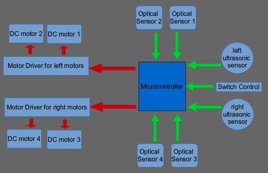
Figure 1: System Overview
General Control
The main control system is performed by the PIC microcontroller 16F877A, this allows satisfactory control the behavior of actuators and signals from sensors. The clock of this microcontroller is limited to 20 MHZ, but this project only uses a clock of 4 MHz. PWM module of the microcontroller is used to control Drivers, the PWM control allow control easily speed of motors.
Flowchart of the algorithm
The flowchart below shows a simple test algorithm implemented in the microcontroller and written in C. The sumo robot wait for 5 seconds according to competition rules, then start to turn right unless detect enemy, when the enemy is in front to sumo robot they attack with the maximum speed and power. This algorithm is simple, only to test the correct functionality of hardware and software involved in the sumo robot.
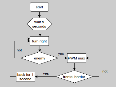
Figure 2: Flowchart
Motor Control
Controlling the DC motors is performed by PWM drivers. Noise can change signal control and produce false meassures o responses, for this reason PWM Drivers are used to be isolated PWM Control Signals and noise from the Motor Power Supply. The next image show this isolation:
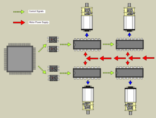
Figure 3: Motor Control
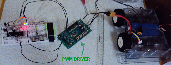
Figure 4: Test of a PWM Driver
Structural Composition
The structure is composed of three layers to get a strong and organised structure. Lower layer is near to the ground because optic sensors shoud be milimeters from ground to get a good response. Intermediate and top layers are compacted to get a low height. A low height approaches the center of gravity down, making it more stable. The next image shows layers:
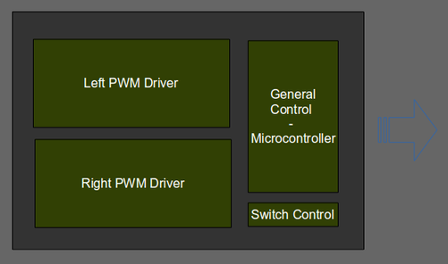
Figure 5: Top Layer
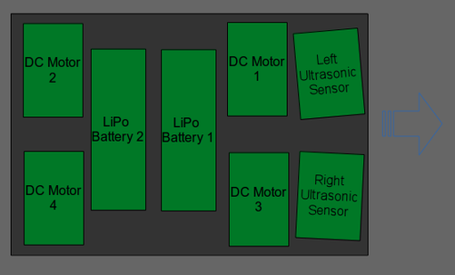
Figure 6: Intermediate Layer
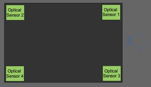
Figure 7: Lower Layer
The next image shows shows the principal component assembly and their location into structure.
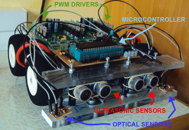
Figure 8: Component Assembly
Then an image is displayed and shows how looks sumo robot after construction.
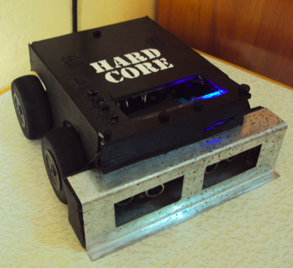
Figure 9: A view of sumo robot finished